|
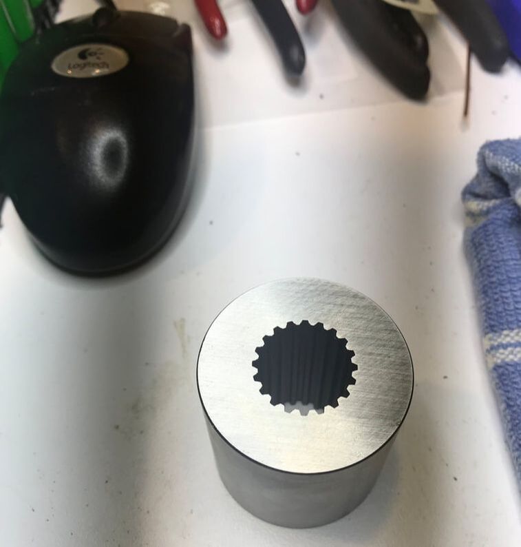
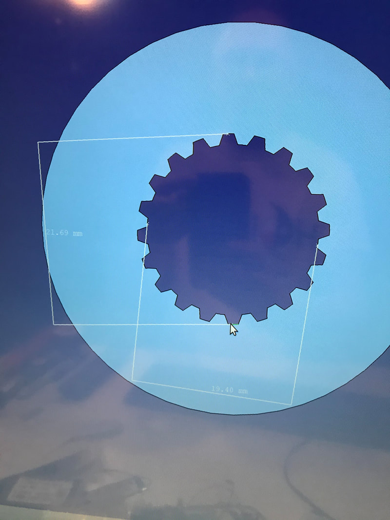
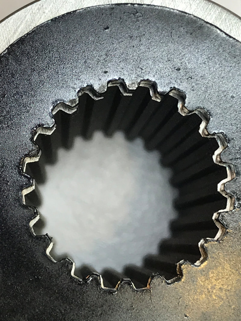
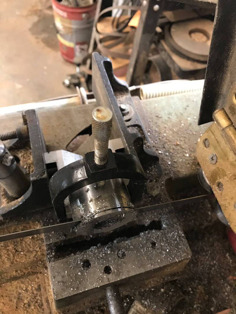
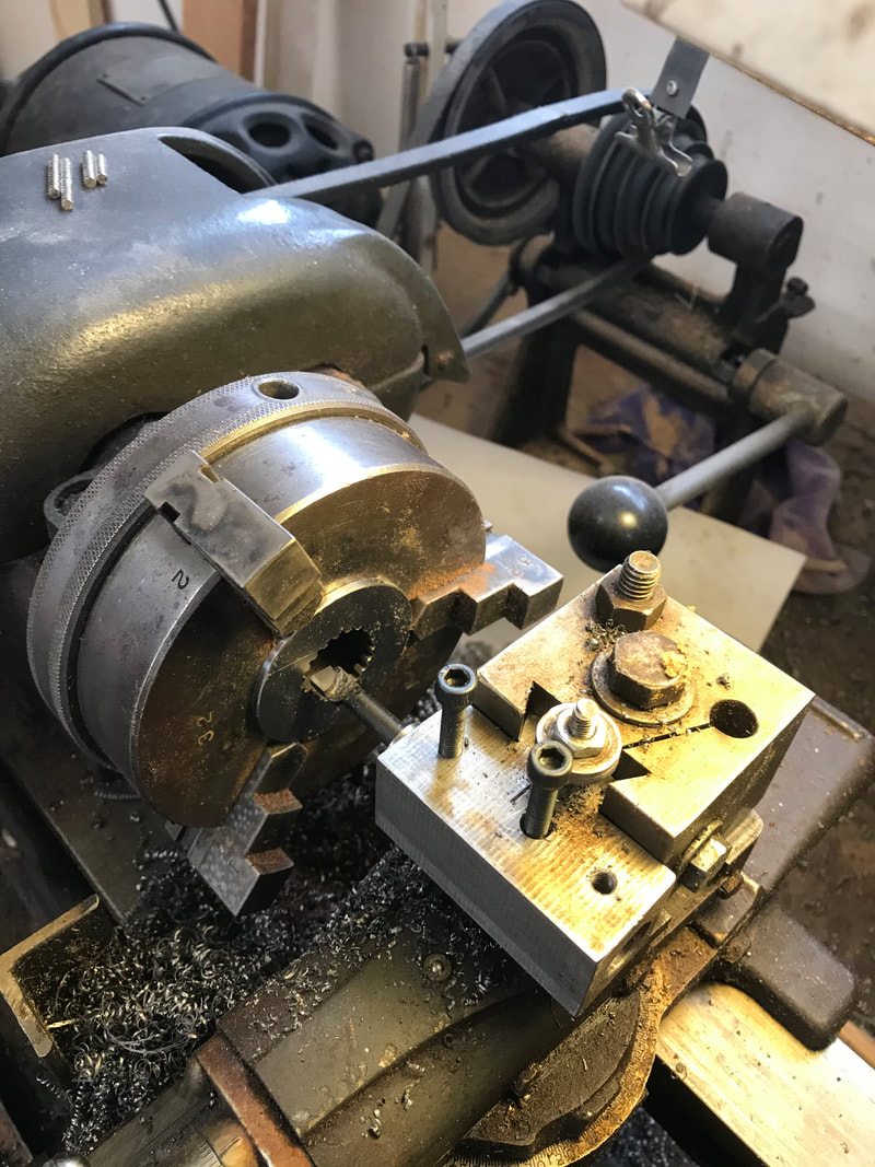
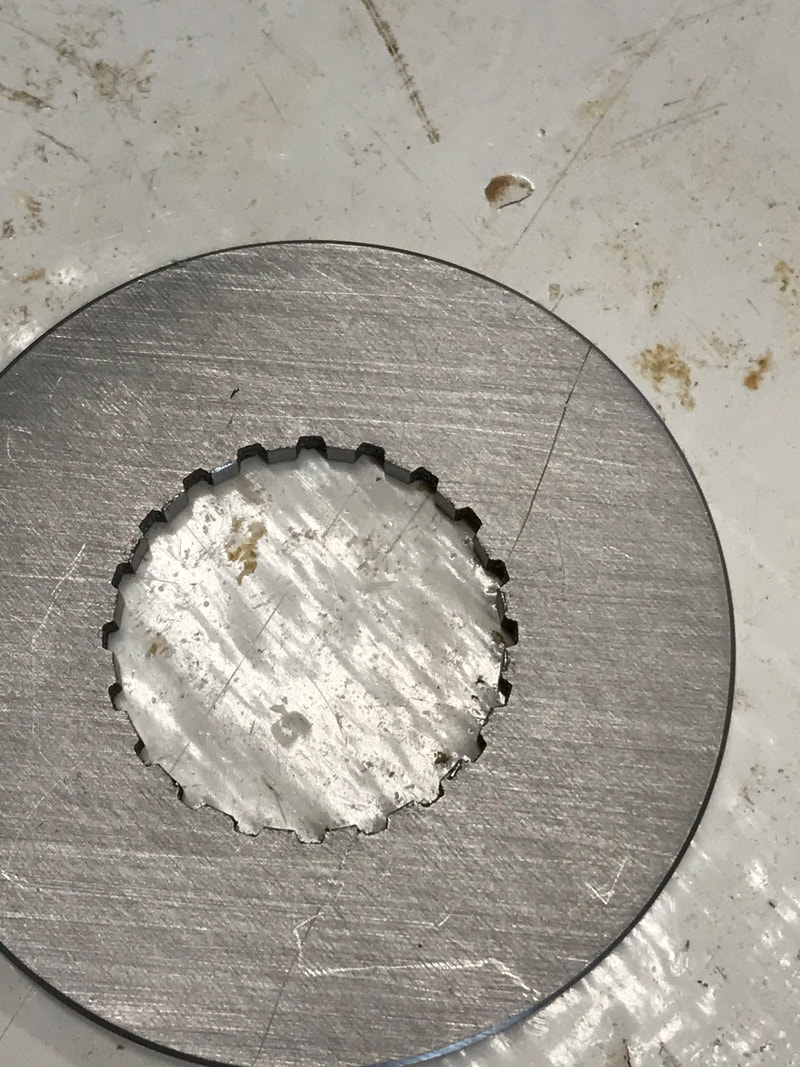
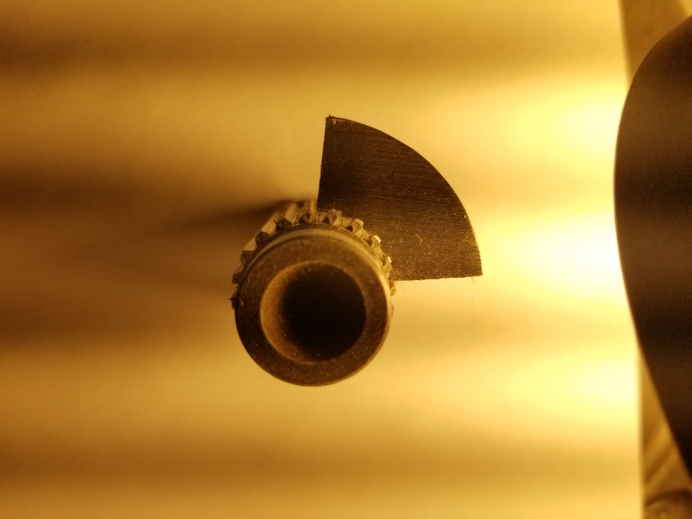
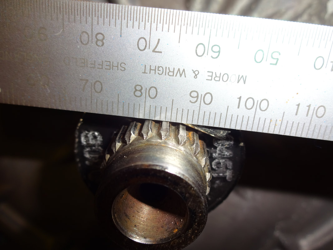
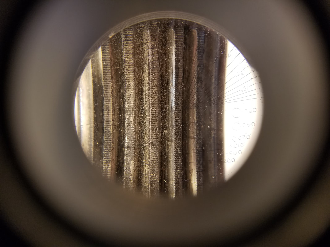
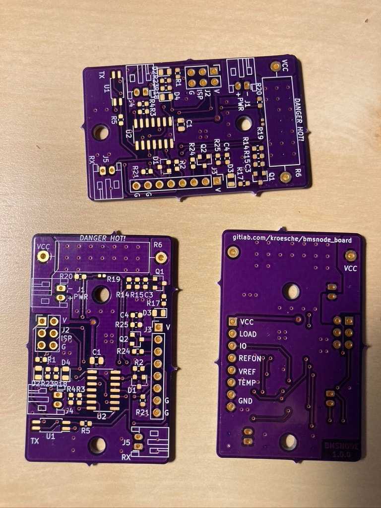
Will this nice looking shiny part, made from 4140 steel, be able to couple the Leaf motor to the Miata or do I have an expensive paper weight? I have a nice paper weight as the coupler doesn't fit. That's a speed bump for our project because a lot of other progress depends on having the coupler ready. When problems occurred in my life, Mom would ask me "What I was going to do about it?" I spent a lot of my childhood with a frown on my face, thinking, dreaming, scheming and planning on how to solve whatever problem was causing issues at the time. The coupler problem produces a visceral "Must solve this" response in me. Imagine me focusing intently with a small frown on my face. My problem solving brain hits overload as all the thoughts burst out. Where did things go wrong? Did the onShape CAD software have a bug? How would we know? Did eMachineShop make a mistake? Did we supply the wrong measurements?. I hadn't planned on getting an education in CAD/CAM, but I think that's what will be happening, at least until the coupler fits the Leaf shaft properly. The first and easiest thing to do was examine the data file file that was sent to eMachineShop. I opened it with a text editor and I couldn't makesense out of it. How about you? #362 = SURFACE_STYLE_USAGE( .BOTH., #621 ); #363 = FACE_OUTER_BOUND( '', #622, .T. ); #364 = CYLINDRICAL_SURFACE( '', #623, 0.0108458000000000 ); #365 = SURFACE_STYLE_USAGE( .BOTH., #624 ); Then I found 'freecad', a CAD program that runs on Linux. I reasoned that if the data file could be read by a program other than onShape, chances were good eMachineShop could read it too. After installation of freecad, I could open the data file and the drawing looked just like the coupler! After a little exploration, I found the measuring tools in freecad and verified the dimensions were the same as what we had used in onShape. The next step was to measure the three physical pieces and compare them with the CAD drawing. 1. The Leaf motor shaft dimensions. 2. The acrylic disk made by Doug, that fit the Leaf shaft 3. The 4140 steel coupler made by eMachineShop I thought we could compare and contrast these for items and make an educated guess on how to correct the fitting problem. I thought "can it really be that simple"? Join me as we find out together what it takes to fix this! First we needed to measure the three physical parts. Ed has better tools than I for measuring. With Sawyer's help, we brought a Leaf motor to Ed's shop so we would have all the pieces to measure in one spot with one tool, hoping for consistent results. Visually, we can see that the steel coupler is smaller than the acrylic version. We needed to know the actual measured difference before we could make any modifications to the CAD drawing. We attempted to use a camera attached to a PC to construct a optical comparison. The lighting, metallic reflections and resolution of the camera killed this option, so we had to try something else. We couldn't see the back side of the coupler, so we decided to slice a thin piece off the coupler. Could we cut 4140 steel on a band saw? I didn't heat treat the coupler, so it shouldn't be "that" hard yet. A test cut with a hack saw revealed we wouldn't ruin a band-saw blade by an attempt. The band-saw did the trick and we had a thin section of the coupler to play with. We already knew the coupler was smaller than the acrylic that fit, so we decided to cut the teeth using lathe. If a wider coupler would fit, we would know that teeth tops radius in the drawing was wrong, with everything else being OK. We turned the teeth down and it still didn't fit, so the problem was more complex. I used Ed's metal calipers to measure each of the three pieces to the best of my abilities. Some of the measurements are harder to obtain than others. Here is what I measured. 1. Leaf shaft Outside splines 21.80 mm or .858" (Valleys in the coupler) Inside splines 19.54 mm or .769" (Teeth in the coupler) 2. Acrylic disk that fits the shaft Valleys 22.01mm or .8665" Teeth tops 19.52mm or .768 3. 4140 Steel coupler Valleys 21.41mm or .8429 Teeth tops 19.38 or .763" Cad drawing Valleys 21.69 or .854" Teeth tops 19.41 or .764 Examining these measurements, we see the 4140 coupler is too small. It looks like eMachineShop got the teeth tops right, but didn't cut deep enough on the valleys. I contacted eMachineShop and they let me know that to return the piece, they require a picture with someone measuring the piece with a caliper. If they agree the measurement seems wrong based on the file submitted, they will pay for shipping and re-make the piece. If they receive the piece and it is correct or within tolerance, then I would have have to pay both shipping costs. Seems reasonable to me. However, fixing the valleys only may not fix the entire coupler fit. I wanted to do some more verification because producing this paper weight uses up $268 and valuable time. After more thinking, Ed decided he still liked the visual approach and put a white sheet of paper over the motor shaft. This increased contrast and covered the reflective metal surface, which allowed much better pictures. Ed then used a better camera and we started to get results usable for optical measurements I discussed the coupler problem with Sawyer over lunch and he asked if we'd included a ruler in the pictures? Wow, I can't believe I hadn't thought of that. Gathering Teresa's 4K camera, a magnet and a ruler, I managed to take some decent pictures of the Leaf shaft Another tool called GIMP was used to measure the high resolution picture. Ed took the picture on the right using a reticule. I'm was finding the valley measurement quite challenging as the manufacturer put a smooth curve on the valley on the shaft so it is hard to tell where the valley edges are. However, using the depth (shaft teeth diameter - shaft valley diameter divided by two), the width of the tooth top, and the teeth angle, the valleys measurement can be calculated. After a bit of reflection, this seems to be one of those problems best solved by iteration. We'll have to start with teeth that fit inside the spline which will produce a loose fit and gradually expand them until we achieve a precise fit. I've started to learn freecad. I'm still not sure what the all the problems are with the coupler and having another way to generate the same part may be handy. In addition, freecad has a python based interface. This would be handy if any iteration is required that has complexity best expressed in a program. I spent a lot of time watching the YouTube tutorials and then trying what I thought I learned. After starting over many times, I've learned the flow of how the designers expected the users to use freecad. I'm not sure where I'd find a gathering of minds that have the experience to solve the coupler problem quickly and accurately. As I don't know anyone who does this for a living, my experience may be perfectly normal. Our current plan is to attempt to used Ed's MySweety clone CNC machine to cut patterns from circuit board material and see how they fit, measuring and adjusting as needed. You can see the coupler problem absorbed most of my attention this week! In other news, the BMS 3.0 boards are here! The boards are here! This is ahead of when oshpark promised them. Joe had already obtained the parts, so we can see if this prototype works or revisions are needed. If this board version works, we can start to research where to get 105 of them made.
The second side of the big battery is 1/2 way done for the paralleling cells step and most of the holes are that side are marked. This will be an ongoing task until everything else is completed. When everything else has problems, it pretty easy to make progress by soldering wires. While I can't say that I'm happy about the coupler, but assuming I can get it solved in a few weeks, it won't impact getting the car running too much, as it takes a while to assemble the batteries. Luckily, I have almost all the battery supplies with me, in case the virus gets bad again. As usual, I can't do this without an awesome team. Thanks to all who listened, commented, supported and worked on it and supported during this week of problem solving. My goals for next week are to get results on the new BMS v3.0 boards, create a software road map, and continue wrestling with the coupler problem. Thanks again for reading. Stay healthy!
0 Comments
Leave a Reply. |
AuthorBill likes cars that understand the 'go fast now' pedal. Archives
May 2022
Categories |
Proudly powered by Weebly

 RSS Feed