|
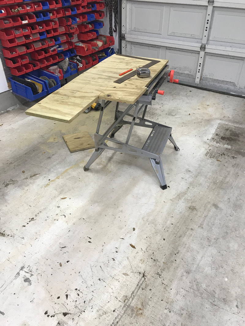
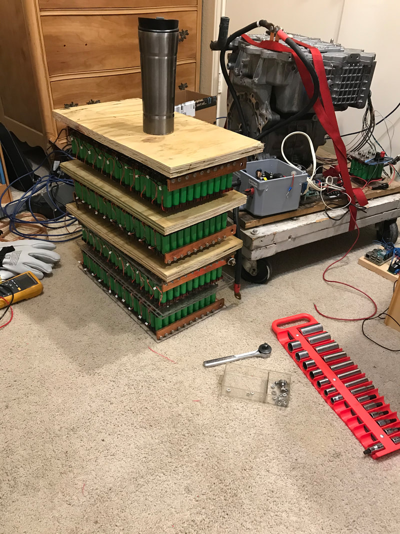
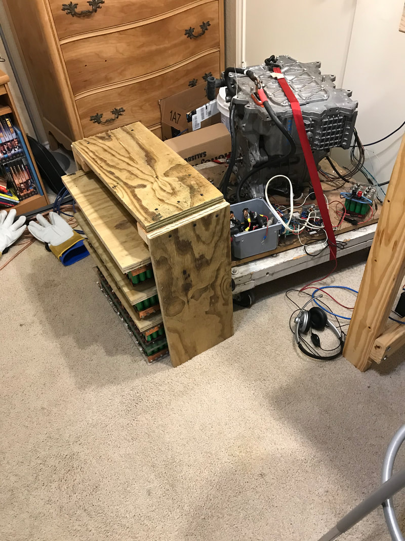
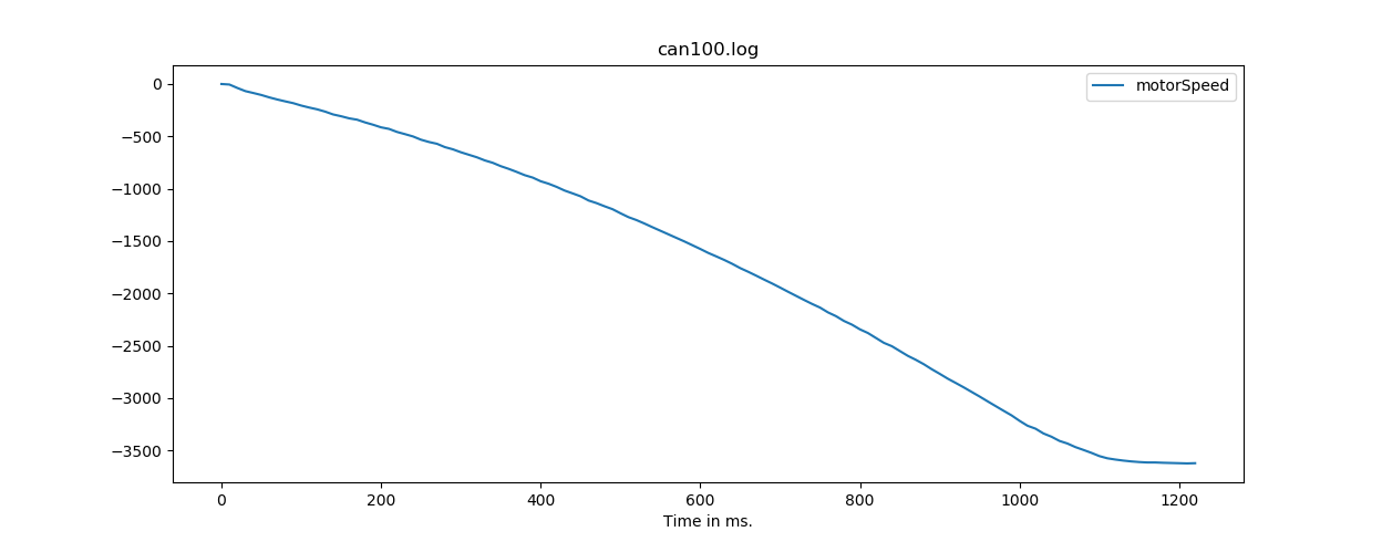
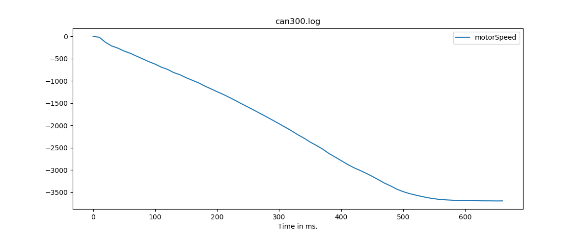
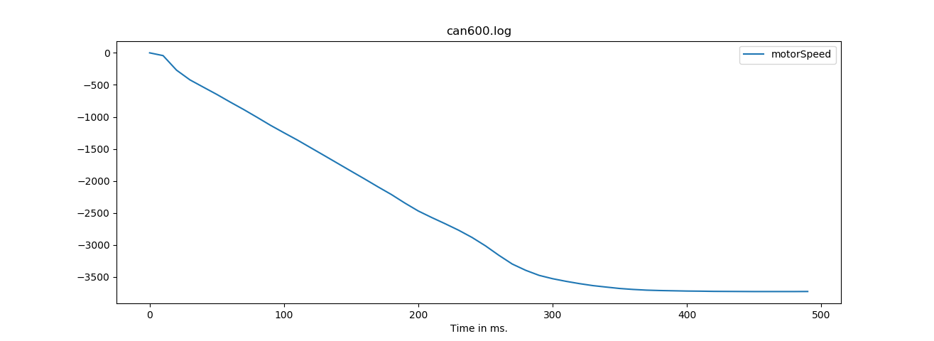
Last week, the goals were to finish battery pack #4, make the six heavy duty cables to hookup the battery to the Leaf motor, start testing with over 10 times the previous amounts of power and make a video to show the motor running. With 'more power' testing being so close and experience soldering the previous three batteries, the forth battery soldering progressed smoothly and by Saturday, I was had the connections and bus-bars installed. The fourth pack took most of Sunday to charge due to having a low current charger and taking time to measure each cell on its first charge. Soon, very soon, I'd be able to to test at a higher power level and see if all the trouble I'd had with inverter faults were caused by the power supply. Teresa and I take the dog for a walk first thing in the morning, and I spied a nice piece of 3/4" scrap plywood laying out to be thrown away. Not having plastic covers for the batteries was going to be a problem, but this plywood could be made to work just fine. Thanks to Ed for supplying the portable work bench that made cutting the plywood that much easier. Here's what I ended up with after connecting everything up. Electric Go KartThat assembled pack stores approximatedly 10 kilowatt hours and can produce 30KW of continuous power. To put that in perspective, my house uses .9 KW under normal conditions and about 4.5 kw when the AC is running. This battery could run the entire house with AC running for about 2 hours or 10 hours with the AC off. Batteries continue to pour out their power until finally discharged. I really didn't want to see what all that power could do in an unplanned arc welding experiment, nor was I interested in getting shocked with 324.8 volts DC. For these reasons, I approached assembling the batteries in to a one larger pack with a certain amount of nervousness. Compounding that nervousness is the fact that working in class 0 linesman gloves is much harder than it looks. The gloves don't fit 100 percent and after all the rubber and leather on top of that, there is very little tactile sensation or control for grabbing nuts and washers or getting those nuts started. Can you imagine a metal nut spinning off to land inside a fully charged pack? Yikes! I hadn't sweated that much doing something that wasn't exercise in a long time. The most nerve wracking connections were the shorter jumpers where one end was being connected and the other end, which now has power, wobbling around as I tightened the connections. Whew. Finally got that done and I took a break to recover before turning to testing. Testing proved to be hugely disappointing as the motor worked about the same as it had with the previous smaller power supply. My theory about what was causing the problem was obviously wrong and I still had a motor that wouldn't work all the time. The frustration must have been evident in my face as my wife suggested taking a break. I groused around the house for a little while before discovering that the guy, Perttu, who authored this web page with the best information about Leaf motors, had replied to my email I sent two weeks ago asking how to retrieve the diagnostic codes. Yay, another way to tackle the inverter fault problem! Now I needed to read some specifications on Unified Diagnostic Services protocol(UDS) (link). Fighting off the feeling of being overwhelmed with yet another complicated thing to learn, I wrote the simplest possible diagnostic program with the main power turned off, expecting to see the under/over voltage diagnostic code. I got lucky and saw the under voltage code listed in the Leaf Technical manual and from there was able to guess at the protocol, which I have to admit I still don't fully understand. If you understand UDS and its CAN implementation, or have significant stock Leaf inverter experience, please contact me. Let me know how it works, so I can make sure I'm doing it correctly and extracting all the diagnostic information as well as correctly clearing the diagnostic codes. Anyone, Ferris? With some more experimentation (this time with the power on!) I was able to produce some combinations which worked well to get this motor spinning. Here's a video of me making the motor go. This week filled with mixed feelings of great joy when it worked and a gnawing frustration when the inverter faulted for unknown reasons. I spent the rest of the week trying to gain an understanding of what the inverter does and doesn't like. I also wanted to get some understanding of how fast the motor could change speeds, because that is what gives you that kick in a car. To that end, I managed to perform some 0-60 tests (specifically 0 - 3500 rpms in reverse) using progressively higher power settings. Here is a set of graphs. These graphs have me predicting that the motor will be able to go from 0 - 3500 rpms at around 100 milliseconds or less. The first graph used a requested torque setting of 100 out a total of 2047, then I increased the requested torque until I reached 600 on the last graph. I stopped increasing power at this point because the motor is not bolted down and I don't have full power on the batteries (30 KW out of the needed 80 KW)
Plans for next week are to work on proportional–integral–derivative controller (PID) control and much more investigation on how to use the inverter without faults while commanding the motor to slow down. Any tips or hints out there are welcome!!! Thanks for reading and stay healthy.
0 Comments
|
AuthorBill likes cars that understand the 'go fast now' pedal. Archives
May 2022
Categories |
Proudly powered by Weebly

 RSS Feed