|
Hello Electrified Miata fans! You may recall our team hitting a speed bump with the Leaf motor coupler. Our goals for this week were to continue wrestling with the coupler problem, get results on the new BMS v3.0 boards, and create a software road map. Our team met all those goals and more! Thank you team. Who knew figuring out the coupler would involve fixing a 'broken face'. I was drawing splines in cad, attaching them to the shaft but I failed to remove the arc, which resulted in a broken face. The only broken face I knew about was failing to block in TaeKwonDo. That could result in a not easily forgotten broken face. Apparently, a broken face can also happen when using freecad. Google and YouTube came to my rescue and using the 'snip' tool I removed the arc which fixed the broken face! Then there were 282 constraints and relationships to deal with. I thought I'd entered some kind of daytime soap opera drama. However, it was much simpler than that. The constraints are used to tell freecad that there are 18 degrees between the center of a coupler tooth and the previous tooth. Since there are 20 teeth on a Leaf shaft, there are 20 constraints. Each tooth has height, angles and relationships with previous tooth. This make a CAD drawing near a work of art. 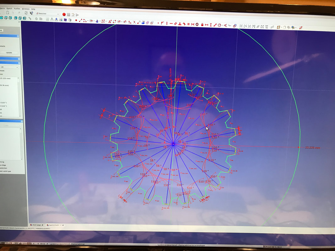 If done in a certain manner, one constraint adjustment can make all the teeth change in size. Since I'm not 100% sure of what measurements I need, I constructed a very thin coupler in freecad with 5 different teeth widths. The thought is, that I can cut the thin coupler into 5 sections each containing 4 teeth and see which one fits the best, if any. After I get the teeth width correct, I can address any other issues like teeth depth or teeth angle in a similar fashion. I've sent the drawing to sendcutsend.com for $30 and we'll see what comes back. After three to four iterations, I should have enough data to send a new drawing to eMachineShop and try again. Details: The CAD coupler is constructed starting with a solid cylinder. Then remove a piece that looks like the Leaf motor shaft to create the coupler. The removal process, or subtraction if you prefer, creates an inverse relationship. That is, the widths of teeth tops on the motor shaft are the widths of the valley on the coupler. Remembering all this and keeping it straight is why CAD experts get paid! On a personal note, I want to thank Doug Kimber for inspiring me to figure the coupler problem out. I was really exhausted (in a good way) from all the CAD learning. Doug is a person who leads by example. He doesn't give up, doesn't let set backs deter him, keeps his focus strong and talks to those who might be able to help. Thanks Doug for your help, mentoring and leading by example over the years. With the coupler problem temporarily out of the way, I returned to the many software tasks. First, Bruce and I produced a road map. 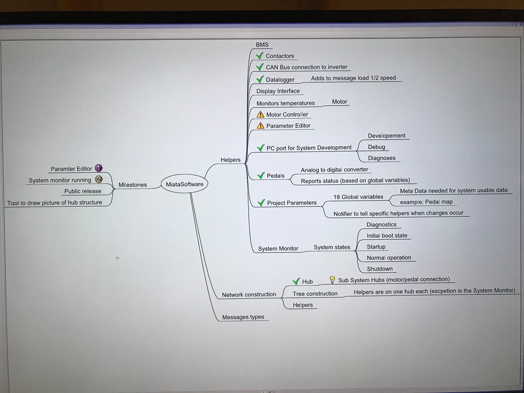 Thanks Bruce for your ability to understand 'Bill Speak' and paying attention to the details! There are plenty of tasks to work on. The first milestone is to get a parameter editor working. There are lots of parameters associated with automobiles and this project is no different. For example, there is a parameter labeled Maximum Regeneration Forward. This parameter controls how much torque is applied when the driver removes their foot from the throttle. In addition to the parameters, there is additional data needed, such as the minimum and maximum range for this parameter. I'm calling that information "Meta Data". Here is a list of the current parameters in our system. My prediction is there will nearly 1000 of these will exist when we are done with the prototype. ACCEL_PEDAL, regenPoint ACCEL_PEDAL, deadUpper ACCEL_PEDAL, deadLower ACCEL_PEDAL, notifyThreshold ACCEL_PEDAL, wotVal ACCEL_PEDAL, offVal, ACCEL_PEDAL, pedalRateDivisor, CRUISE_CNTL, maxTq, CRUISE_CNTL, kP, CRUISE_CNTL, kI, CRUISE_CNTL, kD, MOTOR_CNTL, maxReverseTq, MOTOR_CNTL, maxFwdTq, MOTOR_CNTL, maxReverseRgn, MOTOR_CNTL, maxFwdRgn, MOTOR_CNTL, regenCutoffRpm, PEDAL_MODE, theMode, DIRECTION, theDir, MODE, theMode, Not all of them are relevant to driver preferences, but all need values and a sensible way of adjusting them Joe received the BMS V3.0 boards last week and he assembled one of them. 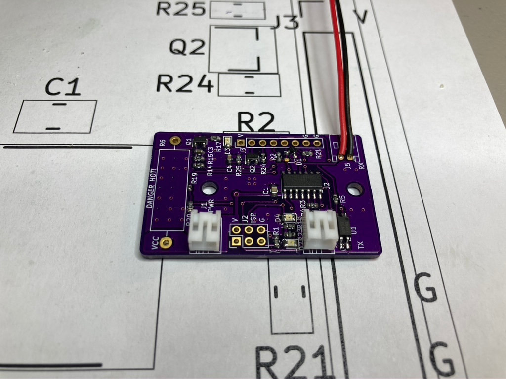 Assembling these boards can be tricky because the parts are so small. The assembled board accepted a program and was able to flash it's LED's. After more testing, it looks the serial receive is not working yet. However, there were hardware changes to this version, so it may be that some software will need to change too. Thanks Joe for bringing the new boards to life! While Joe was busy making new boards, I was busy wrecking the old ones! Not on purpose, but I ended up with two that don't work any more. I started writing the software that talks with the BMS boards. I'd done this before on a previous version so I had something to follow. The protocol is newer. You might ask, how writing software ruined two boards? In the process of hooking up the boards, I discovered that some the the little pig-tails I ordered have their pins reversed.  I suspect that's how I ended up burning up two of the boards. In other news, Bruce had given me the steel estimates for the battery boxes and I was able to pick up steel from Westbrook Metals here in Austin. Westbrook Metals have always been helpful for our projects. I delivered the steel to Bruce. He and Eric are doing the designing, measuring, cutting and welding to make that steel into something we can attach to the Miata. 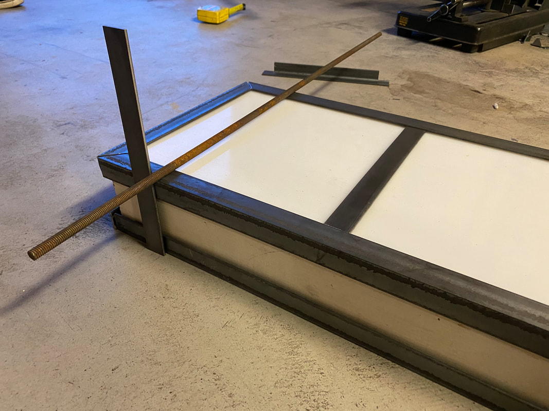 Thanks Bruce and Eric for working even when it's really hot out.
Progress was also made on the big battery pack. Both sides are now soldered in parallel. One side has be marked for drilling. I want to avoid ruining my tools by working on live batteries, so the next task is to drill 700 holes per side where the supporting studs go. My wife keeps saying to video the building process. Would y'all like to see more videos? Next week goals are to finish marking and drilling large battery pack, get more results on BMS v3.0 hardware, get a prototype of a BMS serial node running. I will also be evaluating a coupler slice when it arrives, modify the CAD drawing ordering the next version. Thanks for reading and stay healthy!
1 Comment
|
AuthorBill likes cars that understand the 'go fast now' pedal. Archives
May 2022
Categories |
 RSS Feed