|
Happy Easter to all and hoping this update finds everyone in good health! For those of you following along, last week the goal was to work on battery packs 3 & 4, trying to extract Diagnostic codes from Leaf inverter, testing and interfacing to a 'hall effect' accelerator pedal. I wanted the diagnostic codes, because the inverter would fault quite easily and I would like to know why. I also thought being able to get the diagnostic codes would be handy for any future installation in a car. That problem proved to be harder than it sounds. Apparently Nissan decided they needed extended diagnostics and use a different protocol than the standards. This makes some sense since the inverter is not what a diagnostic unit would be plugged into initially. However, it does make it a bigger challenge to the average hobbyist. I found a program titled 'Caring Caribou' that uses a brute force approach to probe which CAN messages give responses. That showed me that Nissan had their own modes for diagnosis but no further documentation. Since I was getting nowhere fast, I spent a little time capturing the CAN messages from the inverter and writing some code to show me what was happening, when I asked the inverter to spin the motor. Here is a sample of what was captured, and then what it means after translation. (1586219123.827813) can0 1DA#987218000001004B (1586219123.837034) can0 11A#4E4000AAC00002E4 (1586219123.837423) can0 1D4#6E6E000087440123 (1586219123.837775) can0 1DA#983218000001016C (1586219123.847812) can0 1DA#9832180000010266 The first column is a timestamp, the second the Linux interface, the third a CAN message Id, followed by the data. After interpretation, the bytes can be translated. 2020-04-06 19:25:41.643592-05:00: motor rpms at -401.00 2020-04-06 19:25:41.653607-05:00: motor rpms at -415.00 2020-04-06 19:25:41.663603-05:00: inverter voltage at 296 2020-04-06 19:25:41.663603-05:00: motor rpms at -419.00 2020-04-06 19:25:41.673593-05:00: motor rpms at -433.00 2020-04-06 19:25:41.683592-05:00: inverter voltage at 298 In this case, the motor was speeding up in reverse and the bus voltage was going down from its initial start of 304 volts. The data showed me how easy it was to exceed the acceptable bus voltage when slowing the motor down and simararly to draw the bus voltage down during acceleration. It also showed me how quickly these events happened. I feel pretty slow compared to these 10 milliseconds changes, but am anxious to feel how those changes would work in a vehicle of some kind! Most of the variation in voltage seems to come from the fact I'm using a small power supply instead of batteries. It's pretty obvious the Leaf inverter was designed with batteries in mind. I've been working on the batteries every day and making progress. Both battery packs 3 & 4 are finished with step 3 and I'm starting on step 4 for pack 3. On Tuesday, test samples of our cad drawing made in plastic came via mail. 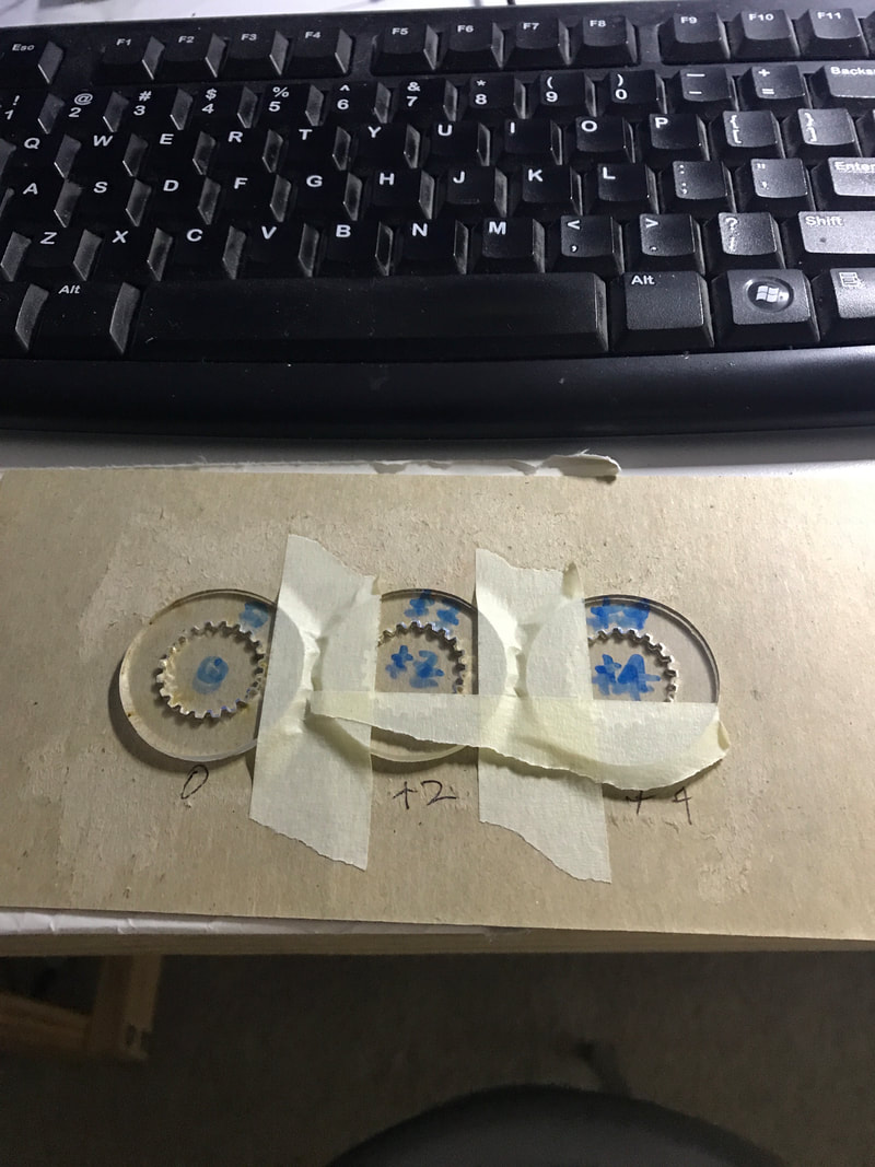 One was too tight, which I broke after a little fiddling around, and 1 was slightly loose. I felt bad about breaking the tight piece, but Doug, who has a great sense of humor said "I guess that proves it was too tight!". It was surprising tough to figure out what the fitment issues were. Good light and lots of magnification are a must. 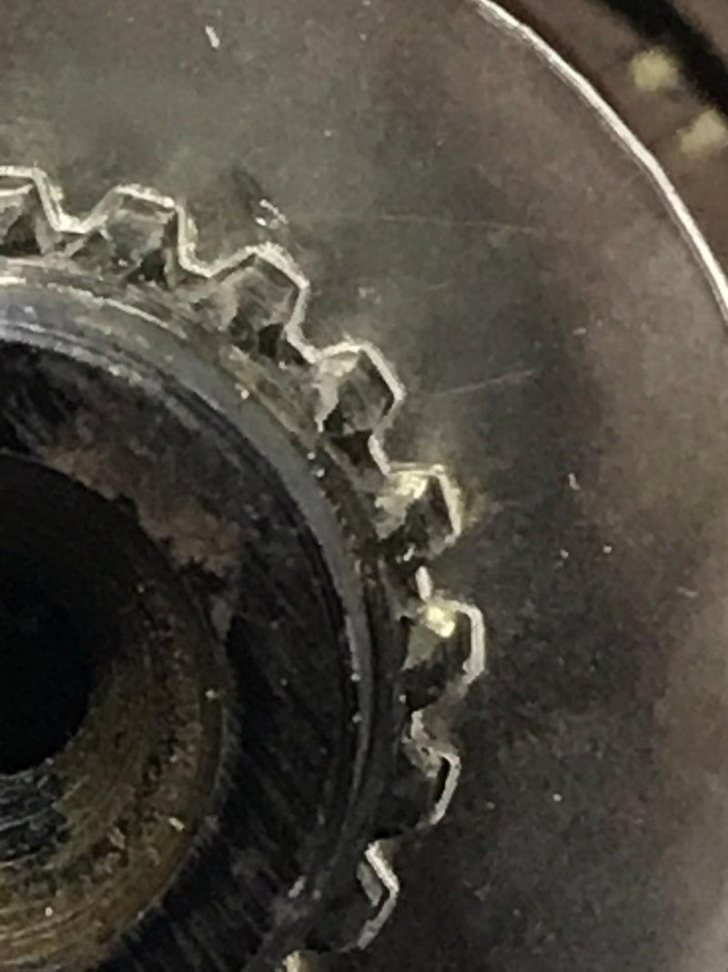 We have a little more work to do, but we're getting closer to a really good fit. Thank you Doug Kimber! Brian had made changes to our display code. With the Shelter In Place order in effect and Doug being in another state, I decided to make a little video showing how display code works with the rest of the system. This shows good progress and we'll be able to accomplish some of the basic things needed to control and examine our system. Thank you Brian! Car night came quickly, and it was time to address the pre-charge time that had been bothering me. The function of the pre-charge circuit is to slowly bring the inverter up to operating voltage. This protects the components of the inverter as well as the contactors, which would see very high surge currents if the pre-charge circuit was not used, prematurely wearing them out. The go-kart turns the pre-charge on for 5 seconds, assumes the the best, that is everything worked perfectly, then turns the main contacts on. With the inverter faulting a fair amount, power cycling is pretty common. It takes a little while to see the fault (Hmmm, maybe I should turn the fault red, lol? ) and then power down and power up. If the inverter has been operated recently, the capacitors are still relatively charged up and would be ready in about a second. Can I do something to reduce the power up time? With the Leaf inverter, the voltage on the inverter is available every 10 milliseconds. I can use this information to make a decision on when to finish the pre-charge cycle and activate the mains. It took a little while to integrate this new pre-charge process but it works quite nicely and ends the waiting for pre-charge cycle. I haven't timed it yet, but seems like between 1-2 seconds depending on if the inverter has recently been powered up or not. One less thing to be bothered about! Now it was time to get to the fun part, using an accelerator pedal to tell the motor to go faster or slow down. Things are different on an electric motor than an Internal Combustion Engine (ICE). With an ICE engine, the throttle position is essentially a speed command, where the engine moves to a certain RPM and will stay there if the throttle position doesn't change and all parts stay together. Closing off the throttle will slow the engine because of compression and less air being allowed into the engine. The case is somewhat different with an electric motor that only has torque commands. First, it has torque in two directions. Negative torque causes the motor to spin in reverse, or function as a generator if the motor is already spinning in the forward direction. Applying a constant positive torque command, the Leaf motor will attempt to spin faster and faster and faster without bound. Of course it takes more power to spin faster, so it is desirable to limit how fast the motor will spin not to mention preserving bearings. In the Leaf motor, if above 480 RPMS (relatively slow), commanding zero torque will simply cause the motor to not speed up any more, but maintain speed. Without a load, I can't really tell if the motor will work to maintain that speed or not. So integrating a throttle with the system proved to be a two part process. The first was converting the voltage from the throttle device to a number, that is converting an analog measurement to digital number. This hasn't very hard dues to other having done this and published their work, thank you very much. I built the circuit and it worked! 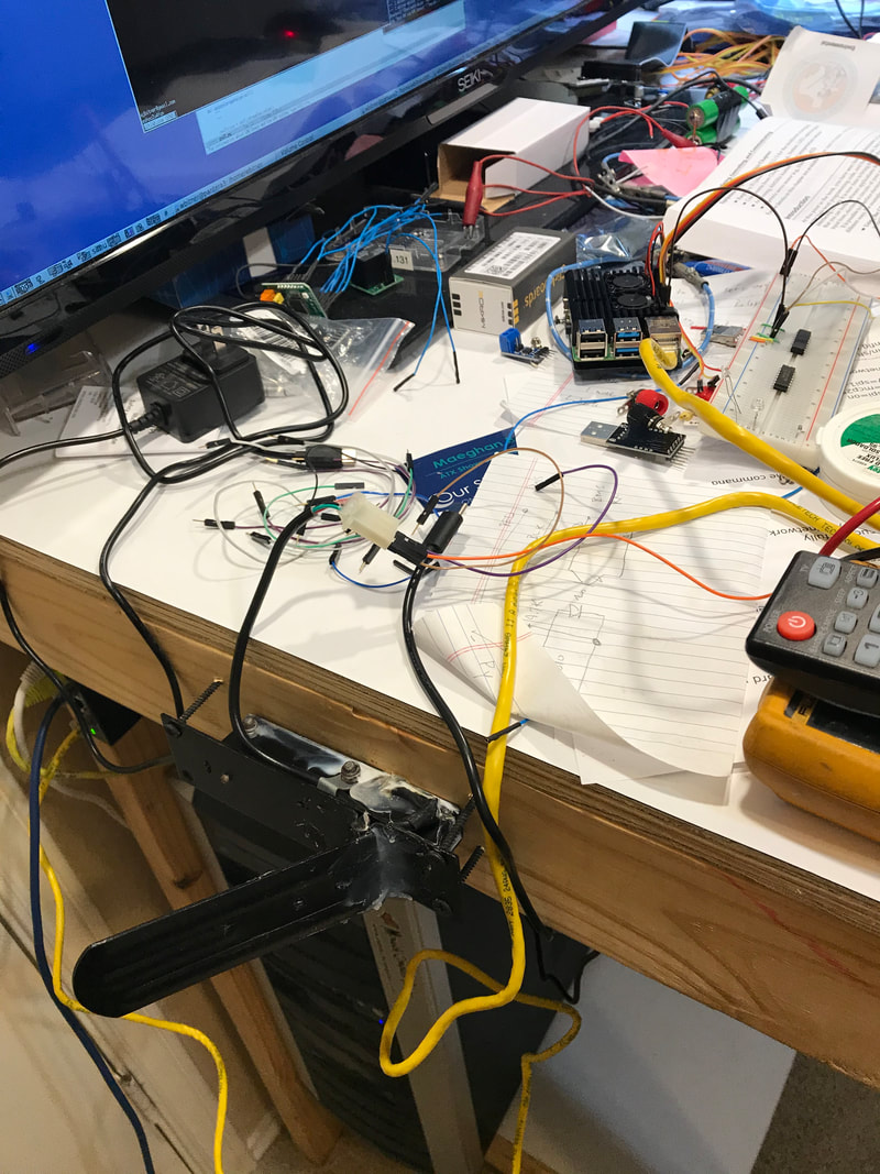 What I didn't count on was a change in values moving it from the inside bench to the garage. This could have happened for multiple reasons. One, it's a bread board, with little pins that don't always make the most reliable connections. Two, buying the cheapest available pedal also may mean the pedal output may drift with temperature changes. Further testing and calibration software will be needed to find out why/when this changes. Then, once I got the motor spinning, I have to apply an opposite torque needed to slow the motor down. The direction of the the torque depends on if we're trying to go forward or reverse. I'm using reverse for now, since the Leaf inverter self limits to 3500 rpms in case my software doesn't work the first time, lol. Going faster than 5000 results in a blown fuse every time. 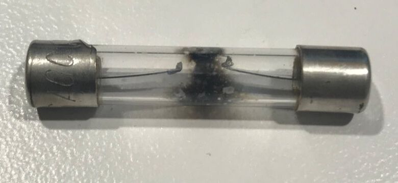 Also, we need to detect how fast the motor is going since if we continue to apply torque, the motor will start spinning in the opposite direction. This means there needs to be another process that monitors the RPMS and the throttle position and make decisions based on those two variables. Luckily, I've written code like this before and was taught some great tricks by Dan Perry, a former boss. It took a little while to get things working properly, but I had made some good progress by the end of car night.
In other news, Joe is taking some time to do a code overhaul on the BMS board. We inherited the software and could make it work, but because it was designed with a different application in mind, we were having a hard time adding new features or changing how some of the old ones work. Sometimes, it's just better starting from the beginning, and that's what's happening now. It may take a little more time, but the BMS functionality will be better suited to our purposes when finished. Thank you Joe for taking this on. Next week, the main tasks are system integration, documentation, batteries. Looking forward, by the time the Shelter In Place orders are rescinded, we'll be looking for vehicle to try this out in. I'm thinking about buying a salvage yard Miata, stripping it down and using that as test vehicle 2.0. It looks like I can get one that's been wrecked for under 1000.00$. Does anyone have experience with this? Thanks for reading and stay healthy.
1 Comment
|
AuthorBill likes cars that understand the 'go fast now' pedal. Archives
May 2022
Categories |
 RSS Feed