|
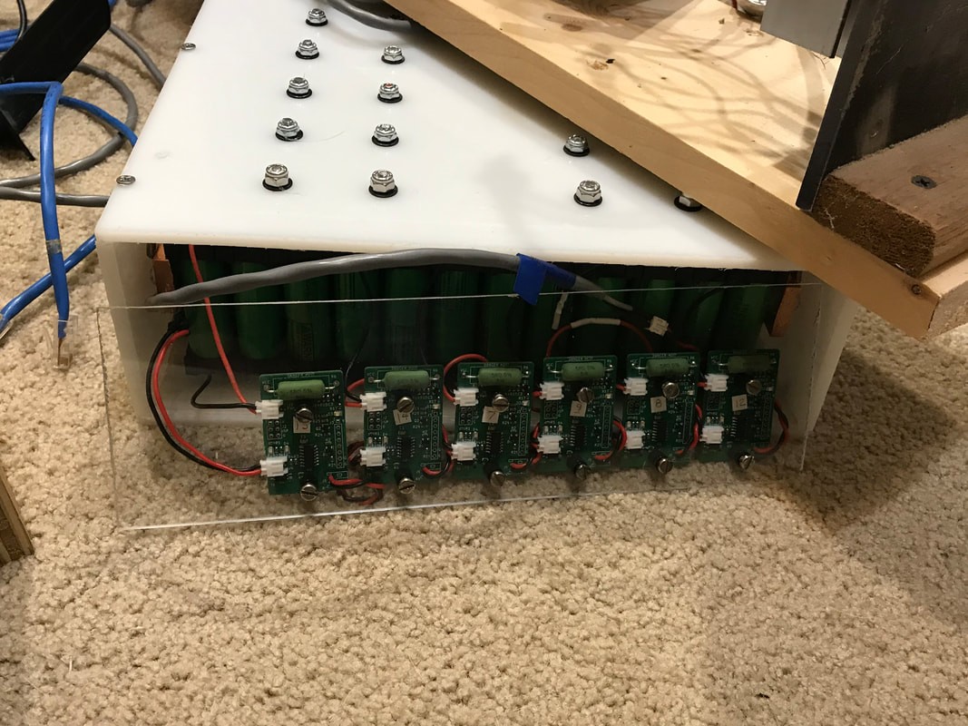
Hello Electrified Miata Fans! We made progress in two major areas of the project this week. We did some major BMS verification while charging one Miata battery pack. We also started on the design of interfacing the Leaf motor to the Miata transmission. Just seeing the motor and transmission near each other in the proper orientation is enough make me exclaim 'Oh Yeah!' and get that big grin. It's been a long project and I'm ready to feel some electric powered acceleration. As my parents would say, the proof is in the pudding! Let's talk about the specifics. 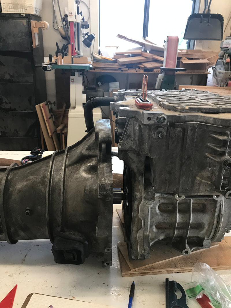 I brought the motor and transmission over to Ed's with Sawyer's help and set them on Ed's clean bench. Locating the proper thickness of shims, we got the motor and transmission roughly aligned. The first thing we noticed is a 2" gap between motor and transmission facing. In some ways, this is handy as you can see the top of the motor bulges where the inverter sits on top. While the inverter doesn't have to sit on top of the motor, for our prototype, there's no reason to make this part more complicated. Bruce, Ed, Brian and I all looked at this and decided that simple rectangular steel tubing can be used to mate these two pieces together. For the shaft, Ed has some 2 1/2" round steel stock that we can use to attach our Leaf motor coupler at one end, and a Mazda pilot bushing and clutch spline at the other end. We'll be spending some quality time with the metal lathe and welding to make that go smoothly. A new pilot bushing is ordered, shipped and due here next week. Once we get the motor coupled and mounted to the transmission, we'll need some charged batteries to run the whole setup. Charged batteries require a BMS, and the BMS starts with those little boards Joe has been designing. Last week we ordered a new revisions of the BMS boards and expect them some time next week. In the meantime, with changes to our boards, Joe also needed to update the test fixture. With an upgraded text fixture, he can deliver BMS boards precalibrated which will make installation easier. I will pick up the rest of the boards that Joe has ready, so we can get busy testing the batteries on the go-kart. One battery is nearly fully charged! We also discovered via assembly, that the connectors for the BMS board really need to be on the back side. As it currently stands, the connectors on the front side have to be plugged in before mounting the boards, which makes me distinctly nervous playing with powered boards and metal screws. What could go wrong? Despite these trials, I have a set of boards mounted on the back and front of a battery pack.
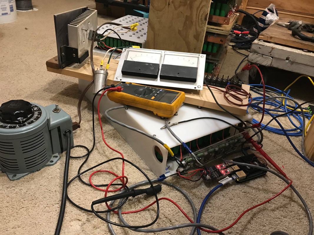
Fully mounted boards allowed me to work on the software side of BMS. I completed the provisioning program and moved on to the monitor program. As soon as I was able to monitor both sides of the pack, I thought everything was great until I looked at the cell information. I discovered that I had mislabeled some of the cells using the provisioning program. No problem, I'll go back to the provisioning program and fix it. Unfortunately, I didn't design for this, so I spent some time enhancing the provisioning program to deal with new boards, or in this case, modifying old information. Once I finished that, I was able to monitor the cells while the batteries charged!!! I'll be joining these 4 test packs together to make 2 Miata 'mid sized' packs and need to avoid overcharging one test pack from the other. 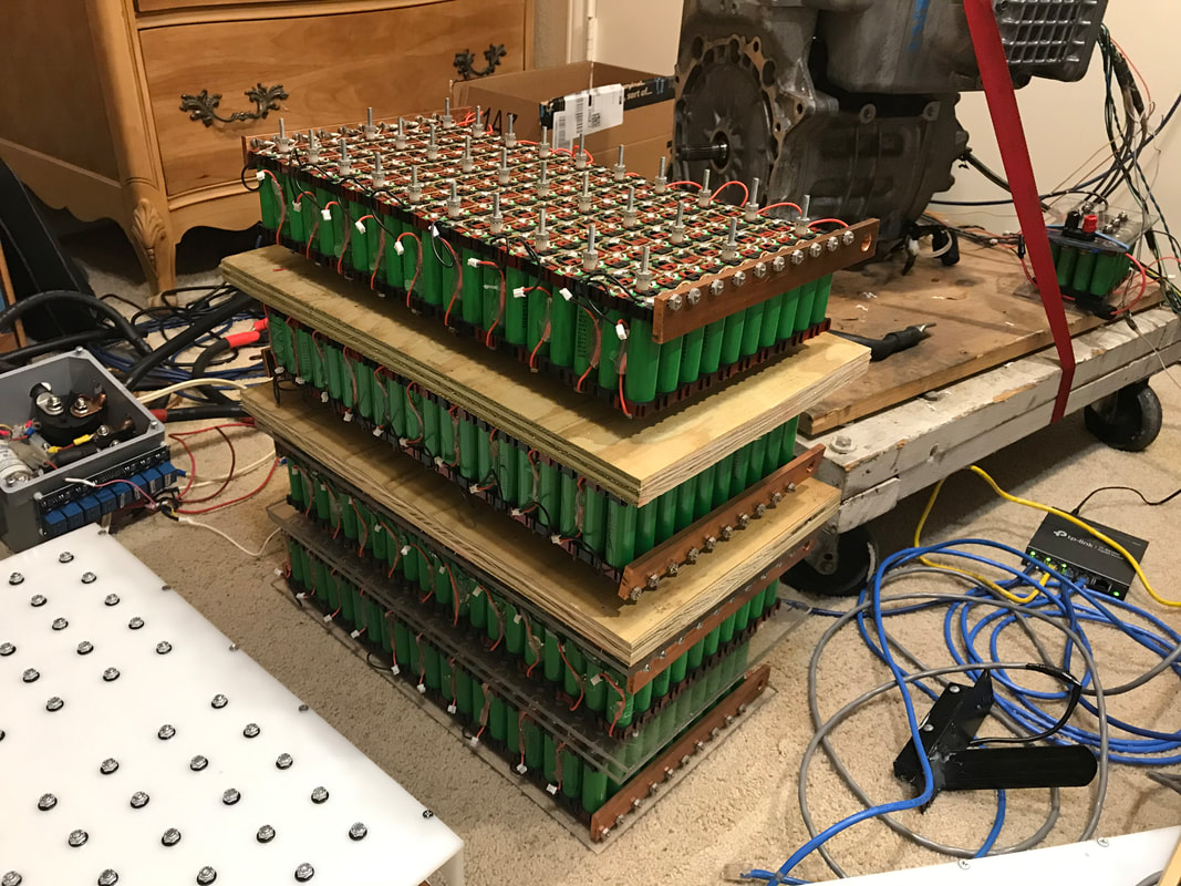 To determine the charging rates, I modifed the charging voltage and studied the current flow in amps to give me data for the following table.
Current (amps) Fluke Meter Volts BMS Volts 0 43.45 43.55 1 43.50 43.55 2 43.55 43.57 3 43.59 43.62 4 43.65 43.62 5 43.69 43.68 6 43.75 43.70 The table shows me the test packs I will join together need to be within 10 millivolts (per cell) of each other to keep the current flow small and less than the maximum charging current. These test packs can discharge 100 amps continuously, but can only charge at maximum of 13 amps. I'll also add 2 additional cells in parallel, which will charge at 2 amps maximum. I'll have to match these 2 cells with the current charge in the test packs. In other news, I met with Dale and Broch Evans. Thanks to Arm Suwarnaratana for the introduction! They are interested in building an electric open wheel race car. While my Miata is not designed for racing, I *like* things that go fast. We had some great discussions and I look forward to following their progress building an electric open wheel race car. Next weeks goals will be to add BMS boards to the second battery, configure and charge it. I'll also pick up metal for the motor/transmission coupling, and start that work. Hope everyone is staying healthy, and having fun! Thanks for reading.
0 Comments
Leave a Reply. |
AuthorBill likes cars that understand the 'go fast now' pedal. Archives
May 2022
Categories |
 RSS Feed