|
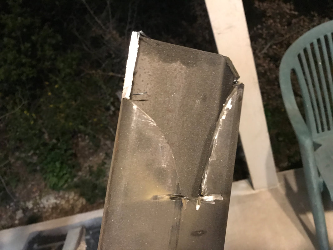
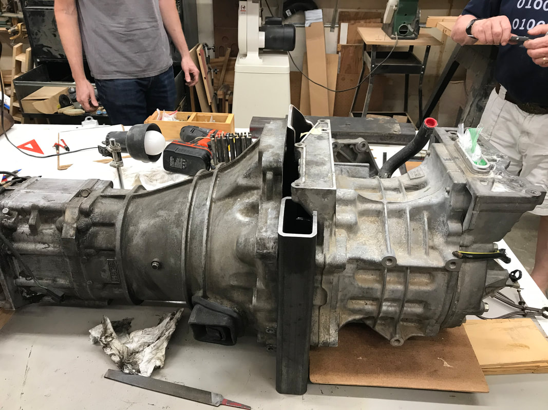
Hello Electrified Miata Fans! Last week our goals were to add BMS boards to the second battery, configure and charge it. That didn't happen, as our short term needs changed. We're going to need to run the motor/transmission combination at Ed's shop. To do that, we'll need a 'portable' DC power supply with at least 250 volts. My test stack isn't that portable, since the bus bars are fully exposed on two of the four batteries. Hmmm, what to do? The need for portable power started when I realized we were likely to make great progress assembling the motor and transmission. Brian pointed out that when mating Joe's motor to his transmission , we spun the motor for alignment and verification. Oh yeah, we *do* need to test it! Spinning Joe's motor (see b2600ev.org) was easy using a 12 volt car battery. Spinning a Leaf motor is a little more involved. Using the stock 2014 inverter, Nissan insists on having 240 volts minimum, else the inverter faults and the motor will not spin. Using my batteries, 240 volts will require a minimum of 72 cells in series. I have two 12S cell packs. The test stand has two 20S cell packs, that ran on the go-kart and are portable. It seemed quite logical to combine the remaining 2 test packs and make one mid-sized Miata pack. The first step was to join the two test packs physically. 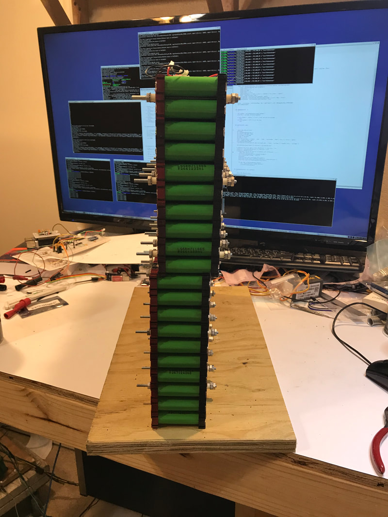 The 2 test packs are about 10 millivolts per cell apart, so they can be joined electrically as well without problems. Each of the test packs has 10 cells in parallel, so I added two more cells after joining them for 22 cells in parallel. 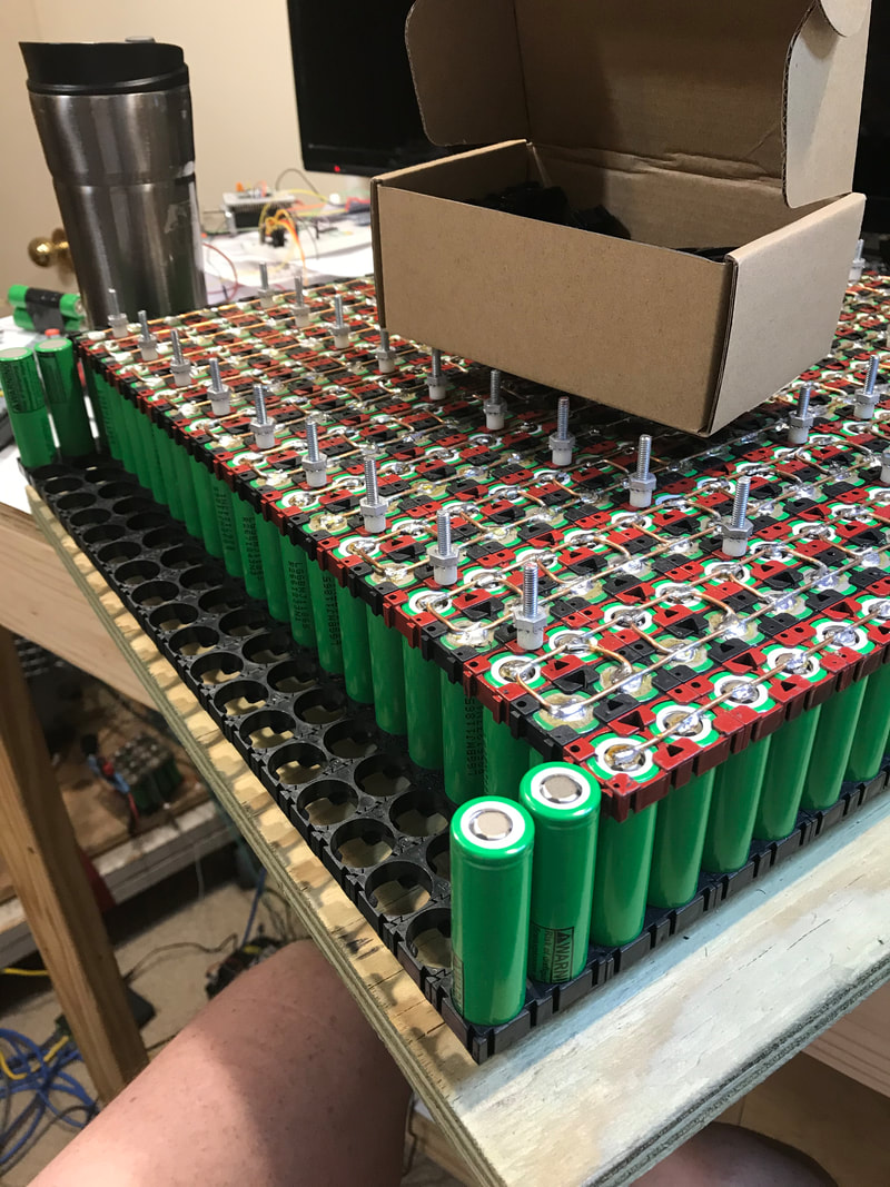 Once the two cells were physically added, I soldered them together and charged them so each cell is within a few millivolts of the rest of the test pack. Next week, I'll join them all electrically and fit the protective plastic covers. Then we'll have another Miata pack and enough portable packs to generate 300 volts. :) One problem solved, onto the next! Ed and I looked at the pilot bearing and the coupler and determined the stock clutch spline wouldn't work for two reasons. The first reason is that it's smaller in diameter than the pilot bearing I have. Once the coupler is bored out for the pilot bearing, we'd have to weld some material to the clutch splines so it was the same size. The stock clutch spline looks to be coated in cadmium, which creates very toxic fumes while welding (the second reason the stock clutch wouldn't work). I had another clutch disk donated to this project from Arm Suwarnaratana. That clutch spline is much larger and is a better fit for the coupler. With the coupler problem given to Ed to make it so, we turned our eyes on the physical attachment between the motor and transmission. Last week, we determined we needed some 2x4" rectangular tubing. I ordered from Westbrook Metals and the metal was ready in two hours. Having all the materials together, we almost had car night! I say almost because a few thing were missing. Joe wasn't there and there was no adult beverages. Drinking with a mask is tough. However, that didn't stop us from making great progress. We marked the 2x4 steel and let the band saw do the hard work. 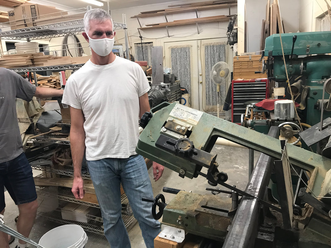 Once the pieces where cut, they had to be customized for the inverter bump. Both Bruce and I forgot our angle grinders. When I asked if Ed had an angle grinder, he reminded me of one of my previous bouts of insanity, when we removed staples from 3000 sq. ft. of maple flooring, some 20 years ago. Ed had an angle grinder and one lone cut-off wheel. This is where Bruce showed his mastery of the angle grinder. 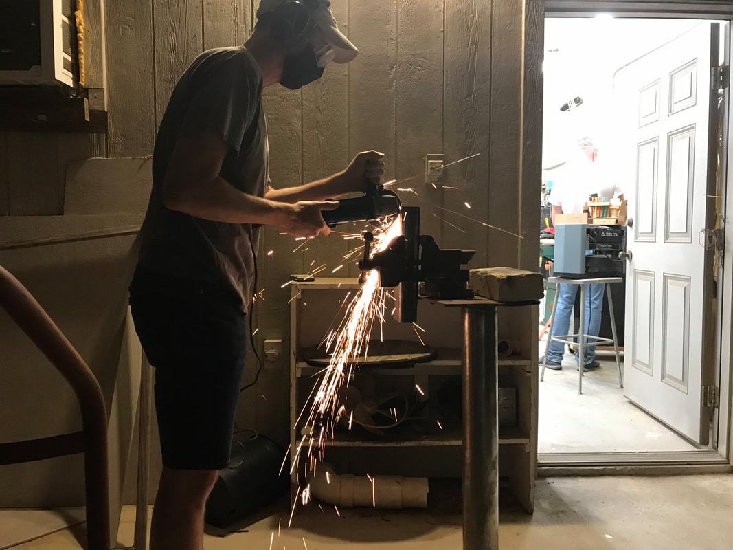 According the project-farm (link), the Makita brand cut-off wheels last a long time and Bruce proved it. That is 1/4" thick steel and he did both cuts using only one disk that was partially used.
Joe might not have been at the shop on car night, but he was also making progress on the project that night. The BMS boards arrived Wednesday and the serial isolator boards arrived on Thursday. While we were cutting metal, Joe was assembling the newest revision BMS board and testing it manually. The first inspection shows the signal between BMS boards to be much better than the previous version. We' ll have to wait until we get 32 of the boards in one string to say we've solved it for sure.
In other news, Ryan Brown and I were able to meet Monday night and get the python code running on his Raspberry Pi. This is the first step Ryan and I have taken towards documenting the code that will run the Miata. Once we were able to get past a few startup issues, everything ran smoothly. It will be so nice to have some documentation to go with the code. But wait, there is still more! I also met with Broch and Dave Evans again. These are the guys who want to make an electric open wheel race car! This time we discussed batteries in depth. The heart(or maybe the stomach in this case) of any electric car is the battery pack. Of course we'd like it all, infinite power, no weight, never needs cooling, will charge in seconds and costs nearly nothing. The reality is we have to choose among these traits. A race car is much different than a street car in that it will need full power for a significant portion of it's duty cycle of on/off throttle. Lucky for us, there are choices. Dave and Broch will do some battery research and real world testing to discover which batteries are most applicable for their style of racing. I'm looking forward to seeing the data and choices. Seeing the battery data will help me when I put 4 motors in the Miata. Four motors is for the future. I still need more data about what one motor will do! Next week we will continue fitting metal, test if motor/inverter works without main power, and finish one mid-sized Miata battery as well as debug the newly updated BMS test fixture and hopefully producing more BMS boards. Hope everyone is staying healthy, and having fun! Thanks for reading.
0 Comments
Leave a Reply. |
AuthorBill likes cars that understand the 'go fast now' pedal. Archives
May 2022
Categories |
 RSS Feed