|
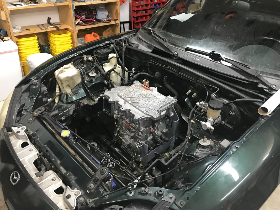
Hello Electrified Miata and Formula Mazda-E fans! This week's action all revolved around one word, reconfiguration. Reconfiguration can apply to software, hardware, design choices or garage space. Join us as we do all of these things in our quest to make our vehicles faster, quieter, more efficient and more fun! Warning: this article contains plenty of technical jargon about speed sensors, programming and Python. Feel free to skip down to 'car night' where the fun happens. Electrified Miata: The goal of decoding the Vehicle Speed Sensor (VSS) is to determine what gear the driver has selected. We want to do this so we can accurately determine what the speedometer should indicate. We also want to determine what RPM the motor must be at when the driver desires to change gears, as we no longer have a clutch. Geek mode On: After last weeks car night, I was left with two software issues to solve for the Vehicle Speed Sensor (VSS). One, the interrupt handling routine took too long at 3 ms. Two, the output from the VSS, post filtered by the MAX9924 is not always symmetrical, meaning the Pico microprocessor has to measure an entire cycle to determine accurate frequency. Frequency can be converted into drive shaft RPMS. Drive shaft RPM's can be compared to the Leaf RPM's and a ratio determined. Since the Miata transmission's ratio is known, we can determine which gear the driver has selected. Let's tackle the first problem. Why did the interrupt handler take so long? My previous Python benchmark experience tells me something isn't right with a 3 ms operation for a very small routine. Perhaps the input/output routines to transfer data between the Pico's Programmable Input Output State machine takes too long? According to the Internet, the input/output transfer is relatively quick and we don't have a reason to dispute this yet. To reproduce the long interrupts times, I constructed a test bench setup and drove the Pico input with a Pulse Width Modulation (PWM) output from the Pi 4. The main (ARM) processor was calling Pythons 'exec' command to run a 'pull' instruction on the PIO. Exec is very cool feature of Python and allows a creative programmer to run self modifying code, but as with any feature, you have to know when to use it. In this instance, the main processor was forcing synchronization with the PIO state machine. Arguably a good thing to do when first learning to control the PIO, but definitely not for speed. Let's reconfigure this code to let the PIO wait on the main processor. I moved the 'pull' instruction into the PIO instructions and included a blocking directive. This makes sure the PIO will wait until there is data in the FIFO. The single change caused the interrupt handler time to decrease from 3 milliseconds to 500 micro-seconds. Much better! On to problem two, capturing the whole asymmetrical square wave. I then experimented with the PIO assembler code to capture the whole wave, versus just the low part of the pulse, since we'd seen that pulse was not always symmetrical. It was very gratifying to change the duty cycle on the PWM and not have the frequency measurement vary! Problem two is fixed and now my VSS problems should be gone. Geek mode lower! My editor (wife) was out of town last weekend and I woke up a little early. Time to go to the garage and test my newly improved VSS code! First, I wanted to reproduce the set up that Joe and I had on car night. I hooked up my scope, but to my dismay, the noise issue was back. Fine. The team had talked about using a filter to remove high frequencies as any little spike can change the frequency measurement. I dug into the parts bin, and using the schematic from https://www.electronicshub.org/active-low-pass-filter/ (thanks Joe), I constructed a 2nd order low pass filter to remove high frequencies from the signal. The VSS won't be generating anything faster than 1Khz with only one Leaf motor. This filter got rid of most of the noise. With my new code, I was ready to write the gear guessing program. The blue 'pip' in the picture below is the interrupt time. 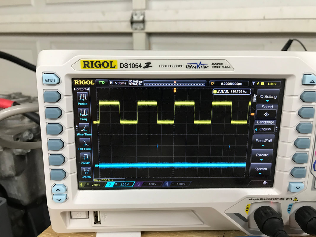 The transmission tells me if it's in neutral or reverse via the Pico. This means that if not in neutral and not in reverse, we must be in gear. If the Leaf motor is spinning and the transmission is in gear, the output shaft will be spinning. We need to ignore spinning slowly, since the VSS doesn't generate a strong signal at low speeds. To prove what is considered low speed, I connected my cruise control (A Proportional, Integral, Derivative loop) program to the system. As a side note, the Leaf motor makes some very unique growling noises if both the cruise control and accelerator pedal argue over what speed the motor should run. In any case, running the output shaft speed below 1000 RPMS generates an inconsistent signal. The MAX9924 has different modes to compensate for this, but the extra complexity involved seems like this is turning into a Rube Goldberg machine. Wouldn't it be easier to put some magnets on the drive shaft and measure the pulse intervals there? The magnets are always full strength and the heat from exhaust that destroys magnets is gone. I'd prefer to use a better input than spending time working around previous design choices that no longer apply. That's one of the bonuses of doing it yourself. We can re-configure when we need too. One final piece of data pushed me to reconfigure test bench setup. While running with cruise control, I shifted the transmission to see what happened without matching the RPMs. It shifted with no problems and no grinding. This is good, since no grinding tells me none of the transmission syncros are destroyed. However, it doesn't allow me to verify if my shifting with no clutch algorithm works. Time to reconfigure the entire garage. Geek mode off! Maybe spinning the wheels would have enough inertia that shifting the transmission without matching the RPMS wouldn't work. Only one way to find out. Get the car with wheels into the garage and install the motor! First we'll have to disconnect everything and start putting all those parts on the new shelves. Car night: By car night, I'd gotten both temporary work tables cleaned off, and it didn't take too much effort to make a space for the Miata. Lucky for us, the Miata is light and easy to roll around, even on a slight grade into the garage. With the car in the garage we dropped the motor/transmission in, but pulled it back out after Dave and Brian convinced me of how much easier it would be to replace the rear transmission seal out of the car. We replaced the seal and re-installed. Everything dropped into place and we held up the transmission with my floor jack. However, to install the Power Distribution Frame (PDF), an aluminum reinforcement that connects the transmission and the differential, we needed to jack up the rear end so we could get under the car. Lucky for us, my neighbor Andy had another floor jack we could borrow. We spent the rest of the night remembering the differential end of the PDF is installed first after the first attempt didn't work. Everything fit together and we'll be starting 'in car' testing soon.
Thank you Andy Bruner for loan of your jack. Thank you Mark Rogawski for lending us your engine hoist. Big thanks to Brian and Dave for crawling under the car and getting the 'fiddly bits' put in place.
Next week, we'll work on installing the driveshaft, motor mounts, rear transmission mount and other miscaellaenous items in preparation of turning the rear wheels with the Leaf motor. Another milestone coming soon. As always, thanks for reading!
0 Comments
Leave a Reply. |
AuthorBill likes cars that understand the 'go fast now' pedal. Archives
May 2022
Categories |
 RSS Feed