|
Hey Electrified Miata fans! This week I'll show how professionals would approach designing a splined coupler. I'll also give a little more background on the newest member of our team, Scott Lambie, and we'll give updates on the major projects underway. Last weeks goals were to coalesce the coupler data, finish the Parameter Editor and verify that multi-board BMS boards are working. I met Scott Lambie, quite a few years at Master Niblock's American TaeKwonDo Association, probably in sparring class. Sparring is a unique activity in that you are trying to kick the other person in the head and remain friends. Sparring forms a special bond because each of us have the power to break boards and bones, yet we don't because we value our sparring partners. Scott's not afraid to step into the ring, not only once, but many Friday's in a row. A big smile crossed my face when Scott contacted me and said he might be able to help with the coupler! Scott had moved to a new job in San marcos working for TB Wood's which make couplers and splines among other things. Occasionally, they are asked to make something for a custom piece. Scott's most recent job is reproducing u-joints that another company decided to stop making. He'd never tried to make a splined coupler, but worked with people who knew the procedure. There are one of two ways professionals generally do this. The first involves making a mold using dental cement and using an optical comparator to measure the results. 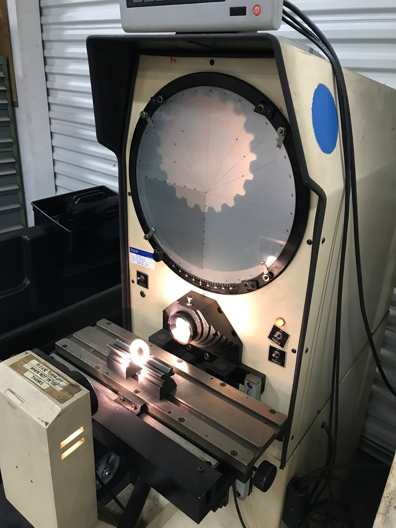 The second method involves setting two different size 'pins' in between the teeth of a spine and measuring the difference in height. Since I didn't have any dental cement laying around, and Scott had access to pins, we chose the second method. Using pins of known dimensions, the angle of the spline teeth can be calculated. See page 111 of this PDF for the gory details.  The magnets helped hold the pins in place while we measured with a micrometer. By knowing the outer and inner dimension of the spline and the angle between the teeth, the dimensions for a coupler can be calculated. The important factors in measuring are that the pin must set in between the teeth, not on top or touching the bottom. On the Leaf motor, this can be tricky because the splines are small. Scott did the measuring and I did the note taking. We measured in three locations around the spline, with each measurement having and inner and outer number, in case the spline was angled. We used 'blade' micrometers, which I had never seen, to find the inner dimension of the spline. We also used a fillet gauge, another tool I'd never heard of, to measure the radius of the bottom of the spline. 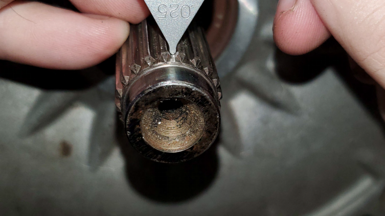 I got a tour of the factory and saw a bunch of cool tools, met some friendly people and had a great Saturday, chatting with an old friend.
Because of Covid, this seemed like a really large outing! Thanks Scott for showing me around and teaching me how the professionals do this job. When Scott ran the calculation to find the angle, it appeared that either the angle was not 20 degrees, or we used too large of a pin for our measurements. After more thought and comparing with the internet drawings, we figured out the larger pin was .002" bigger and was sitting on top of the splines. Just like learning a new move in sparring class, the theory don't always work the first time in practice. Now I really know why someone might charge a fair amount to figure out an unknown spline! Last week, Doug had printed a coupler slice made on his 3D printer based on https://github.com/angusjo/leaf-splines. This nifty piece of plastic arrived and it didn't fit. However, I could see that the fitment issue was different from the other couplers I'd tried. 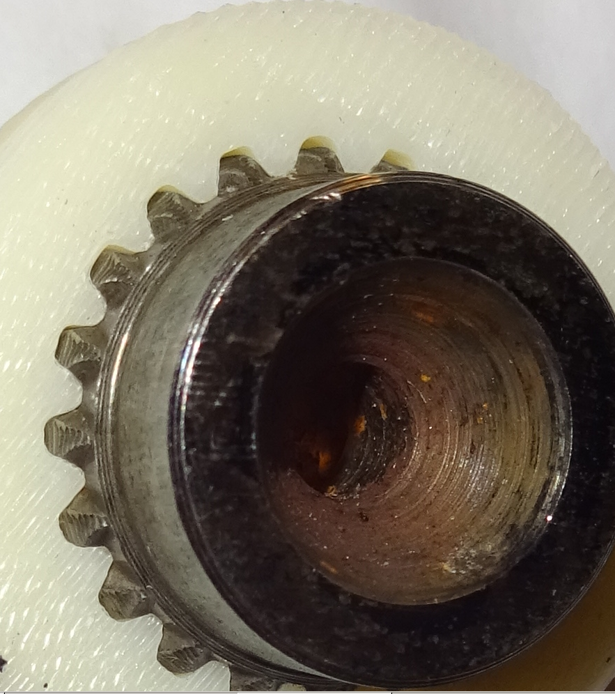 This coupler was rubbing on the bottom, that is the 'teeth' were too tall. Based on all available data, thanks to the combined efforts of Doug and Scott, I made my best guess and sent another drawing to SendCutSend. That coupler slice will be here next week and we'll proceed from there. I have an 80 percent confidence level that this coupler slice will fit. Thanks Doug and Scott! You may remember Bruce and Eric helped move the Miata to their shop. They have been working like mad to fit and mount the battery boxes in the rear. There is a lot of cutting, grinding, welding and hole drilling involved. Metal working takes time, not to mention wearing heavier clothing for welding during the summer heat. Look at how nice these batteries fit. 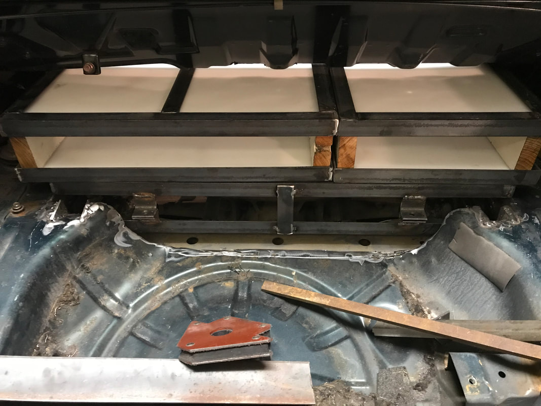 This part of the job isn't without it's own challenges. Miata metal is thin, which is why the car is so light. This makes it a tough to weld since the metal simply evaporates when you put any power into it. Thanks Bruce and Eric for making this happen. Joe continued verification of our new BMS boards. The next test was to assemble them in a string, which meant soldering and completing two more boards. Once each board was working he put them in a string and started more testing. A few bugs were found, fixed and it looks like everything works! Joe also verified our additional I/O pin works by powering a cooling fan since the resistor gets pretty hot trying to dissipate nearly 5 watts of heat in a small space. 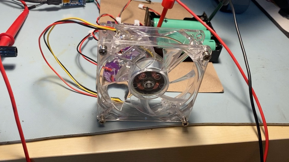 We'll implement Pulse Width Modulated shunting to keep the temps down as well as a few cooling fans. We may need the cooling fans for the batteries themselves, or the battery boards when shunting if the balancing requires more power within a reasonable amount of time. We just ordered 30 of these new boards. Way to go Joe!
With the rest of the team getting all this great stuff done, I needed to make some real progress on the Parameter Editor. This was a bit more challenging than I expected. I learned some new tricks in Python, despite having programmed with it for over twenty years. Geek mode on: The parameters get updated on the fly and the user code specifies a callback function to be executed when updates occur. In this case, the callback functions didn't exist. I could generate all them each time, updating the code when a new parameter was added, or have the computer generate them as needed. Self modifying code, which was a lot of fun for me. End Geek mode. Thanks to Teresa for doing the tough job of Editing. The rough draft I give to her only makes sense to me and she has to add details, re-arrange the order and give examples to make this blog what it is. Writing is hard for me, and I get grouchy when I'm unable to express myself clearly in text. You might think after 57 years, I'd have gotten over simple frustrations, but I have more to learn in this area. Thank you Teresa for all you do! Thanks to this amazing team for all the progress. The goals for next week are to do more battery soldering, work on a few software problem I observed while testing the Parameter Editor, and evaluate the new coupler when it arrives. Thanks for reading! Comment!! Stay healthy and have fun.
0 Comments
Leave a Reply. |
AuthorBill likes cars that understand the 'go fast now' pedal. Archives
May 2022
Categories |
 RSS Feed